Quick Technical Summary
A comprehensive cantilever rack installation guide outlines the sequential mechanical erection of freestanding structural steel storage towers engineered for long, unwieldy materials such as steel pipes, lumber packs, bar stock, and structural tubing. Assembly begins by joining heavy structural I-beam bases to vertical columns on the floor using high-strength structural bolts torqued between 150 and 250 foot-pounds. Once hoisted vertically, columns are stabilized through horizontal struts and diagonal X-bracing panels, anchored into minimum 6-inch 3,000 to 4,000 PSI concrete slabs, and fitted with load arms calibrated at an upward pitch of 2 to 4 degrees to counteract deflection under full static payload.
Key Engineering Takeaways
- Horizontal Assembly First: Always bolt the column and base together horizontally on the warehouse floor before lifting to ensure complete bolt torque access and worker ergonomics.
- Plumb Alignment Tolerance: Vertical column lean must not exceed 0.25 inches over 10 feet of vertical height, or a maximum of 0.5 inches over the total column elevation.
- Slab Embedment Standard: Anchoring cantilever bases requires heavy-duty 5/8-inch or 3/4-inch concrete wedge anchors embedded at least 4.5 to 6 inches into uncracked concrete slabs.
- Upward Arm Incline: Cantilever arms must feature a built-in upward pitch of 2 to 4 degrees so that when the arm deflects under load, the storage plane remains level or slightly positive.
- Cross-Bracing Tensioning: Diagonal turnbuckle tension rods and horizontal channel struts must be installed and squared before any concrete anchors are drilled and torqued.
Pre-Installation Planning and Concrete Slab Verification
Unlike standard pallet racking systems that feature four corner posts per bay, a cantilever rack relies on a single vertical spine to support massive outward-projecting loads. The resulting rotational moment transfers extreme overturning tension directly into the front and rear baseplates.
Before uncrating steel components, installation contractors must verify that the warehouse concrete slab satisfies engineering load specifications. Standard commercial cantilever installations require a concrete slab thickness of at least 6 to 8 inches with a minimum compressive strength of 3,000 to 4,000 PSI.
Contractors must also survey the installation floor for saw-cut control joints, cold pour seams, and expansion cracks. Anchors must never be drilled within 6 inches of an expansion joint or slab edge. Facilities planning mixed storage yards frequently review a foundational pallet racking system engineering guide to coordinate cantilever aisles alongside standard pallet storage rows.
Tools and Rigging Equipment Required
Erecting industrial cantilever towers weighing several thousand pounds requires certified material handling equipment and heavy industrial hand tools. Gathering all necessary apparatus before starting prevents hazardous delays during column elevation.
- Calibrated pneumatic or electronic torque wrench capable of reaching 100 to 300 foot-pounds.
- Rotary hammer drill with 5/8-inch and 3/4-inch carbide-tipped masonry drill bits.
- Optical transit, self-leveling multi-plane rotary laser level, and magnetic torpedo levels.
- Forklift with certified boom attachment or overhead bridge crane with nylon lifting slings and clevis shackles.
- High-strength structural steel drift pins, alignment spud wrenches, and dead-blow hammers.
Every worker on site must wear personal protective equipment including steel-toe safety boots, high-visibility vests, and hard hats. Reviewing baseline racking system safety tips and OSHA rules ensures the work zone remains compliant throughout the entire erection process.
Step 1: Assembling Columns to Bases on the Floor
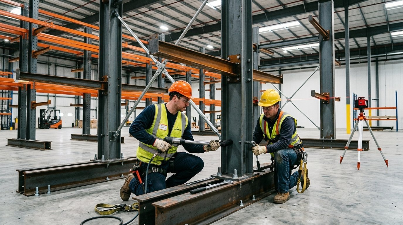
The safest and most efficient method to assemble a cantilever column and base is horizontally on the concrete floor. Attempting to bolt a heavy base to an upright column while standing vertically creates severe tipping risks and uneven bolt tensioning.
Place two heavy wooden dunnage blocks on the floor to support the vertical column channel. Position the structural base beam against the column bottom flange, aligning the factory-punched bolt holes.
Insert structural bolts through the base and column flanges, placing hardened steel flat washers under both the bolt head and hex nut. Most manufacturers utilize heavy structural bolts conforming to ASTM structural bolt specifications to handle continuous dynamic bending stresses.
Tighten the bolts incrementally in a crisscross pattern using an impact wrench. Finish with a calibrated manual torque wrench, checking each fastener against the manufacturer specified torque value, typically between 150 and 220 foot-pounds. For additional staging insights, installers often compare these techniques with general racking system installation safety procedures across warehouse bays.
Step 2: Column Elevation, Rigging and Squaring
Once the base-to-column connection is fully torqued on the ground, the assembly is ready for elevation. Rigging must be attached above the center of gravity to prevent the base from swinging wildly during the lift.
Rigging and Lifting Protocols
Wrap a heavy-duty synthetic rigging sling around the upper portion of the column, approximately two-thirds of the way up the mast. Connect the sling to a forklift crane jib or overhead hoist using a rated screw-pin shackle.
Slowly hoist the column upward while a ground technician guides the base along the floor. As the column approaches vertical, ensure the bottom flange settles gently onto the chalk line layout without jarring the concrete slab.
Keep the crane or forklift rigging attached to the column until temporary braces or horizontal struts are securely pinned in place. Never allow an unanchored, unbraced cantilever column to stand unsupported under OSHA general materials handling standards.
Plumb and Level Tolerances
Using a precision magnetic level or optical laser, verify that the column is plumb in both the front-to-back and side-to-side planes. The vertical column must stand perpendicular to the floor within 0.125 inches per 10 feet of height.
If the concrete slab slopes or contains surface dips, insert full-contact steel leveling shims beneath the baseplate. Never use thin washers or partial shims that create uneven point loading under the structural base beam.
Step 3: Installing Horizontal Struts and Diagonal X-Bracing
A single freestanding cantilever column has zero lateral stability along the aisle direction. Structural stability is achieved by tying multiple columns together into rigid bays using horizontal structural channel struts and diagonal tension X-bracing.
Horizontal Strut Assembly
Erect the second column assembly parallel to the first, spacing the columns according to the engineered bay width, typically 48, 60, or 72 inches on center. While both columns remain supported by lifting equipment, connect the bottom and top horizontal channel struts between the column webs.
Secure the horizontal struts with Grade 5 bolts and prevailing-torque locknuts, leaving them slightly loose until all diagonal members are fitted. These horizontal struts establish the exact centerline spacing for the entire rack run.
Diagonal X-Brace Tensioning
Install the diagonal cross-bracing rods or angle irons between the upper and lower horizontal struts. If the system utilizes threaded turnbuckle tension rods, hook the rod clevis ends into the structural mounting tabs.
Tighten the turnbuckles alternately while monitoring the bay with a diagonal tape measure. Measure from the top left corner to bottom right, and from top right to bottom left. The bay is square when both diagonal measurements match within 0.0625 inches.
Once diagonal measurements are verified, tighten all strut bolts and turnbuckle jam nuts securely to form an interlocking structural frame conforming to Rack Manufacturers Institute installation standards.
Step 4: Concrete Slab Floor Anchoring Procedures
With the entire column bay plumbed, leveled, and cross-braced, the structure can now be permanently anchored into the warehouse floor. Anchoring is the single most critical step in resisting the forward tipping moment created by cantilever arm loads.
Drilling Anchor Holes
Using the pre-punched holes in the column base as a template, drill vertical holes into the concrete slab using a heavy rotary hammer drill. The drill bit diameter must match the anchor diameter exactly, typically 5/8-inch or 3/4-inch.
Drill to a depth at least 1 inch deeper than the required anchor embedment, typically 5 to 6 inches total depth into a standard industrial slab. After drilling, use compressed air and a wire masonry brush to blow all concrete dust and debris out of the hole. Leaving pulverized dust in the hole reduces anchor pullout strength by up to 40 percent.
Torquing Wedge Anchors
Thread the nut onto the wedge anchor until the top of the nut sits flush with the top of the threaded stud to protect the threads. Drive the anchor through the baseplate hole into the concrete using a heavy hammer until the washer sits flat against the steel base.
Use a calibrated torque wrench to tighten the anchor nut to the manufacturer specified installation torque, typically 85 to 110 foot-pounds for 5/8-inch anchors and 150 to 175 foot-pounds for 3/4-inch anchors. Facilities combining long-material cantilever racks with wide carton pick shelves frequently reference bulk storage racking load capacities to establish balanced warehouse anchoring schedules.
Step 5: Cantilever Arm Installation and Incline Pitch Setup
Cantilever arms project horizontally outward from the column, serving as the direct load-bearing shelves for stored inventory. Installing arms requires careful attention to connector styles, safety pins, and upward pitch angles.
Arm Connector Mechanisms
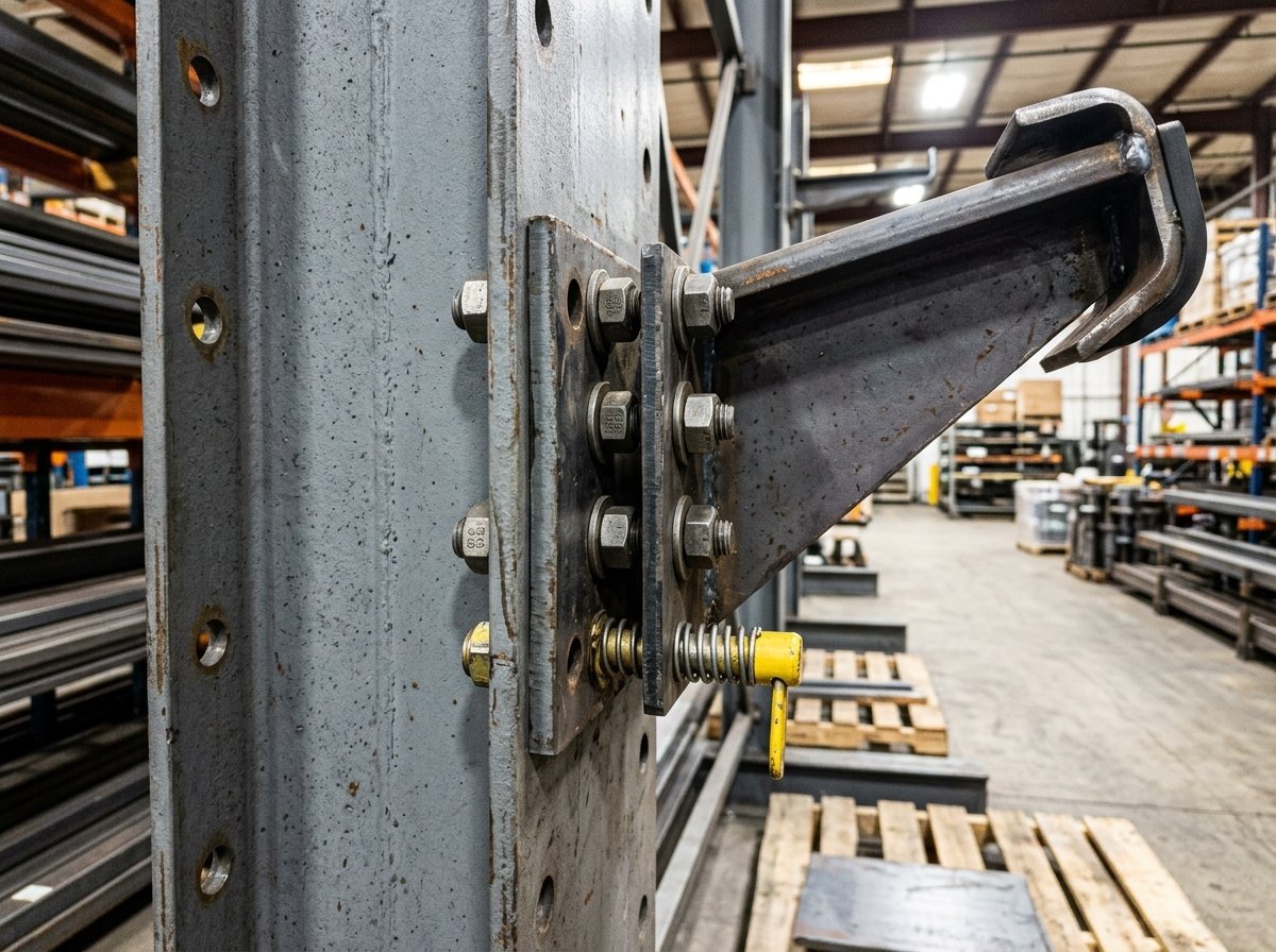
Manufacturers utilize two primary arm connection styles: bolt-on arm brackets and pin-locking wedge connectors. Bolt-on arms feature heavy structural steel saddle plates that wrap around the column face and secure through multiple horizontal Grade 8 bolts.
Pin-locking arms feature welded multi-tooth brackets that seat into vertical column punch holes, secured by a heavy steel safety pin and spring cotter. Ensure safety pins or locking bolts are fully engaged before placing any load onto the arm.
The Upward Incline Pitch Rule
Cantilever arms must never sit completely flat or angle downward when empty. All quality cantilever arms are fabricated with a built-in upward pitch or camber of 2 to 4 degrees (approximately 0.5 to 1 inch of rise over a 48-inch arm length).
When a heavy bundle of steel tubing or lumber is placed onto the arm, the steel naturally flexes downward under mechanical bending strain. The initial upward camber ensures that under full rated load, the arm deflects to a horizontal plane rather than angling down, preventing products from sliding off the front.
To inspect arm deflection and structural geometry across diverse installations, facility engineers frequently study the broader cantilever racking system engineering overview for component sizing rules.
Step 6: Pipe Stops, Arm Lips, and Decking Accessories
Storing round materials such as steel pipes, PVC conduit, or copper tubing requires secondary retention accessories to prevent products from rolling off arm ends.
Removable Pipe Stops
Most cantilever arms feature vertical sockets welded onto the outer tip of the arm. Installers insert square or round steel pipe stops measuring 4 to 8 inches in height into these sockets.
Removable stops allow forklift operators to pull the stops out during side loading and reinsert them once the bundle is safely seated on the arm. Fixed welded lips are also common on arms dedicated to lumber packs.
Drop-In Wire and Steel Decking
When cantilever racks are repurposed to store short crates, skids, or irregular pallets, drop-in wire decking or corrugated steel panels are installed across adjacent arm tiers. Decking panels bridge the gap between arms, transforming open cantilever bays into continuous wide-span shelves.
Installers must ensure that drop-in wire decks rest flush against arm support angles and feature downward-curling waterfall lips to prevent lateral shifting. Outfitting rack ends with heavy-duty column protectors detailed in pallet rack accessories and column protectors shields exposed cantilever corners from lift truck impact.
Engineering Installation Specifications Table
The following engineering table summarizes standard mechanical specifications, bolt torque requirements, and alignment tolerances for commercial cantilever rack installations.
| Component Connection | Fastener Grade | Required Torque | Alignment Tolerance | Inspection Method |
|---|---|---|---|---|
| Column to Base Beam | ASTM A325 / Grade 8 | 150 to 220 ft-lbs | Flush Flange Contact | Manual Torque Wrench |
| Floor Wedge Anchors | Grade 5 Carbon Steel | 85 to 175 ft-lbs | Min 4.5 in Embedment | Torque Check After 24h |
| Horizontal Struts | Grade 5 Machine Bolt | 65 to 90 ft-lbs | Centerline ±0.06 in | Tape Measure Check |
| Diagonal X-Brace Rods | Forged Steel Turnbuckle | Snug Locknut Tight | Diagonals Equal ±0.06 in | Dual Corner Measurement |
| Cantilever Arm Pitch | Lock Pin / Grade 8 Bolt | Pinned / 120 ft-lbs | 2 to 4 deg Up-Angle | Digital Inclinometer |
Following these torque values and alignment tolerances prevents structural fastener loosening under repetitive forklift loading cycles.
Distribution managers coordinating multi-building expansions often review warehouse storage solutions layout planning to ensure clear drive aisles surround all cantilever installations.
Post-Installation Commissioning and Safety Audit
Once mechanical assembly and anchoring are complete, the installation team must conduct a formal commissioning audit before releasing the rack for inventory placement.
Pre-Loading Verification Checklist
Inspect every individual structural connection systematically across the following items:
- Confirm that all base-to-column bolts remain fully torqued and show zero thread stripping.
- Check that every floor anchor is securely seated without cracked concrete around the baseplate perimeter.
- Verify that all arm safety locking pins and cotter clips are completely inserted and locked in place.
- Confirm that turnbuckle jam nuts on diagonal X-bracing are tightly cinched to prevent vibrational loosening.
- Ensure the vertical columns exhibit zero twist or out-of-plumb lean exceeding engineering thresholds.
Capacity Plaque Placement
Under ANSI and RMI safety regulations, every cantilever rack system must feature visible capacity plaques mounted on the end columns. These plaques must clearly state the maximum load rating per arm, the maximum load rating per column side, and the maximum allowable bundle length.
Operators must be instructed never to exceed rated arm capacities and to distribute long loads evenly across at least two to three arms to prevent concentrated point-load failure.
Frequently Asked Questions
Can a single-sided cantilever rack be converted to double-sided?
No, standard single-sided cantilever bases are engineered with forward-projecting legs that rely on the rear column spine. Converting to double-sided storage requires replacing the base with a double-sided structural base beam that extends equally in both directions to prevent overturning.
How far apart should cantilever columns be spaced during installation?
Column spacing depends on the rigidity of the stored material. For flexible items like thin conduit or light lumber, columns should be spaced 48 to 60 inches apart to prevent material sagging. For rigid structural steel I-beams or heavy bar stock, column spacing can extend to 72 or 96 inches on center.
How thick does a concrete slab need to be for cantilever racks?
Most industrial cantilever rack installations require a minimum concrete slab thickness of 6 inches with 3,000 to 4,000 PSI compressive strength. Heavy-duty outdoor lumber yards or structural steel towers reaching over 20 feet in height frequently demand 8 to 12-inch concrete slabs with rebar reinforcement.
Why do cantilever arms have an upward pitch?
Cantilever arms are fabricated with an upward pitch of 2 to 4 degrees to counteract natural mechanical deflection. When heavy inventory bundles are placed onto the arm, the steel flexes downward, resulting in a level storage plane that prevents round items from rolling off.

Callum Langham
Callum Langham is a warehouse storage consultant and structural racking specialist with over 14 years of hands-on experience specifying, installing, and certifying commercial storage solutions across North America.